

Governors in Marine Diesel Engines: Working Principle, Types, Speed Droop, Hunting and Overspeed Trip
Governors in Marine Diesel Engines: Complete Guide
A governor is an important speed-control device used in marine diesel engines. Its primary function is to automatically control engine speed within prescribed limits and maintain the required speed when the engine load changes.
In a marine engine, the load is not always constant. Changes may occur because of rough sea conditions, rolling and pitching of the vessel, and changes between loaded and ballast conditions. The governor responds to these load variations by adjusting the fuel supply to the engine.
This article explains the working principle, types of governors, speed droop, hunting, sensitivity, stability, hydraulic governors, electronic governors, isochronous control and overspeed trips from the provided marine engineering study material.
What Is a Governor?
A governor is a device that automatically controls the speed of an engine within prescribed limits.
Once the engine speed has been set, the governor attempts to maintain that speed despite variations in engine load.
For a marine diesel engine, this is achieved by controlling the rate of fuel supply. When the engine requires more power, the governor increases fuel supply. When less power is required, it reduces fuel supply.
Simple Definition
Governor: A device used to automatically maintain the speed of an engine by regulating fuel supply according to load changes.
Why Is a Governor Required in a Marine Engine?
The load on a marine engine can change continuously.
For example:
- Rough sea conditions can change propeller loading.
- Rolling and pitching can affect the engine load.
- The ship may operate in loaded or ballast condition.
- Sudden changes in propulsion load can cause engine speed fluctuations.
Without proper speed control, these changes could result in excessive variations in engine RPM.
The governor therefore continuously senses engine speed and adjusts fuel supply to maintain stable operation.
Basic Principle of a Marine Engine Governor
A diesel-engine governor generally consists of two important systems:
- Speed-sensing arrangement
- Hydraulic unit for controlling fuel supply
The speed-sensing arrangement detects changes in engine speed. The control mechanism then changes the fuel supply through the fuel pump or fuel rack.
Basic Control Sequence
Engine speed changes → Governor senses change → Control mechanism operates → Fuel supply changes → Engine speed is corrected
This creates automatic speed regulation.
Important Governor Terminology
Understanding governor terminology is important for marine engineering examinations.
1. Offset
Offset is the difference between the measured engine speed and the set speed.
2. Idling Speed
Idling speed is the speed of an engine when it is operating at no load.
3. Full Load Speed
Full load speed is the engine speed when the engine is operating at its rated continuous power.
What Is Governor Speed Droop?
Speed droop, or governor droop, is the reduction or change in engine speed from no-load condition to full-load condition.
The difference between no-load speed and full-load speed is called governor droop. It is expressed as a percentage of the maximum rated speed.
Formula
Droop % = [(No-load rated speed − Full-load rated speed) / No-load rated speed] × 100
A common droop value is approximately 4% according to the provided material. For example, if full-load rated speed is 1800 RPM, the no-load rated speed would be approximately 4–5% higher, around 1875 RPM.
Why Is Droop Important?
Droop helps provide stable engine operation and prevents unnecessary corrective movement of the governor.
It is particularly important for generators operating in parallel because it allows load sharing between generator sets.
What Is Governor Hunting?
Hunting is the continuous fluctuation or swinging of engine speed above and below the mean operating speed.
In simple words, the governor repeatedly increases and decreases the fuel supply instead of settling at a stable position.
Causes of Hunting
According to the provided material, hunting can occur due to:
- Excessive governor sensitivity
- Incorrect or faulty compensation-system setting
- Air in the hydraulic system
- Worn-out linkages
Why Is Hunting Undesirable?
Governor hunting can cause:
- Wear of linkages
- Variation of engine load
- Fluctuation in RPM
- Fluctuation in generator voltage and frequency
In an auxiliary engine, such fluctuations can affect precision navigation equipment such as gyroscopes and radar.
Therefore, stable governor operation is important for reliable marine-engine operation.
Governor Sensitivity
Sensitivity is the ability of a governor to respond quickly to changes in engine speed from the set point.
It indicates how closely the governor can maintain the engine speed near the desired value.
However, increasing sensitivity excessively can cause hunting.
Governor Stability
Stability is the ability of the governor to quickly reach a new equilibrium position and maintain that position.
There is an important relationship between sensitivity and stability:
Higher sensitivity → lower stability
Therefore, the governor must be properly adjusted to achieve the required balance between quick response and stable operation.
What Is Dead Band?
Dead band is a narrow range of speed variation in which the governor produces little or no corrective response.
During the dead-band range, the governor does not correct the fuel-pump rack position.
A small dead band is useful because without it, even a very small speed change could cause the governor to act continuously and potentially produce hunting.
Governor Compensation
Compensation is a temporary change in the speed setting during a load change.
The purpose of the compensation system is to improve governor stability and achieve steady-state speed control.
It involves two actions:
- Droop application – as the fuel supply changes.
- Droop removal – after the engine responds to the fuel change and returns toward its original speed.
Mechanical or Direct-Action Governor
The provided diagram on page 4 shows a simple direct-action governor. It is a purely mechanical governor operating on the principle of centrifugal force.
Main Parts Shown in the Diagram
The diagram includes:
- Governor spindle
- Flyweights
- Carrier
- Spring
- Gear-driven mechanism
- Linkage to the speed-control mechanism
Diagram.
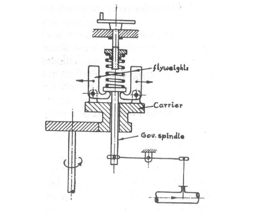
Working of Mechanical Governor
The governor spindle is rotated through a gear mechanism connected to the engine shaft.
As the engine speed increases, the flyweights rotate faster and move outward due to centrifugal force. Their outward movement depends on engine speed.
A spring opposes the centrifugal movement of the flyweights and attempts to return them toward their original position.
The resulting movement causes the governor spindle to move vertically. This movement is transmitted through the linkage to the engine speed-control mechanism.
Advantages of Mechanical Governors
- Simple construction
- Few moving parts
- Relatively inexpensive
- Suitable where extremely accurate speed control is not required
Hydraulic Governor
Hydraulic governors are more sophisticated than simple mechanical governors.
Although they have more moving parts and are generally more expensive, they provide:
- Higher sensitivity
- Greater power to operate the fuel-control mechanism
- Ability to be adjusted for similar speed operation under different loads
A hydraulic governor combines mechanical flyweights with hydraulic control.
Working Principle of Hydraulic Governor
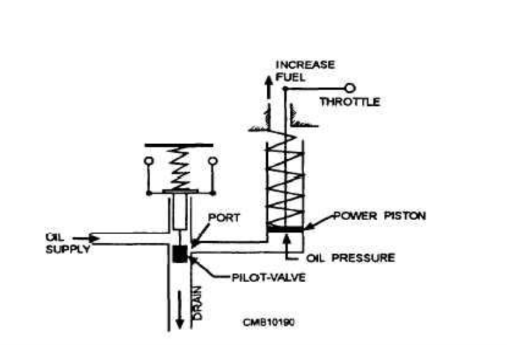
The provided hydraulic governor diagram on page 6 shows the relationship between the flyweights, pilot valve, oil supply, power piston and fuel-control mechanism.
At Normal Operating Speed
When the governor is operating at the control speed or balanced condition:
- The pilot valve closes the port.
- Hydraulic oil flow is stopped.
- The power piston remains in its required position.
Therefore, the fuel setting remains steady.
When Engine Load Increases
When engine load increases:
Engine speed falls → Flyweights move inward → Pilot valve moves downward → Oil port opens → Pressurized oil enters power piston → Power piston moves upward → Fuel supply increases
The increase in fuel supply raises the engine power and brings the speed back toward the required value.
When Engine Load Decreases
When engine load decreases:
Engine speed rises → Flyweights move outward → Pilot valve moves upward → Oil flows toward drain → Spring pushes power piston downward → Fuel supply decreases
Reducing the fuel supply helps bring the engine speed back toward the required value.
Advantages of Hydraulic Governors
The provided material lists the following advantages:
- High power output
- High efficiency
- Easy maintenance
- Suitable for diesel engines operating in parallel, such as auxiliary engines, and applications where multiple engines drive a single propeller through gearing.
Disadvantage
A simple hydraulic governor can be inherently unstable and may continuously make unnecessary corrective movements, resulting in hunting.
Hydraulic Governor with Feedback
The problem of hunting in a simple hydraulic governor is associated with the time delay between governor action and engine response.
The provided material explains that speed droop is commonly used to improve stability. It ensures that the engine throttle reaches a particular position for a given speed and load, thereby reducing unnecessary governor movement and over-correction.
Electronic Governor in Marine Diesel Engines
Modern marine engines may use electronic governors for accurate engine-speed control.
An electronic governor uses a closed-loop feedback system to control fuel supply according to changes in engine speed and load.
The three major components described in the PDF are:
1. Speed Sensor
A Magnetic Pickup Unit (MPU) is positioned near the engine flywheel.
As flywheel gear teeth pass the MPU, an electrical signal is generated. The voltage and frequency are proportional to engine speed.
2. Electronic Control Unit
The ECU receives the speed signal from the MPU and compares it with the desired speed setpoint.
It uses a PID — Proportional, Integral and Derivative — control algorithm to calculate the required correction to fuel supply.
The ECU then sends an electrical command to the actuator.
3. Actuator
The actuator converts the electrical command into mechanical movement.
It controls the engine fuel rack to increase or decrease fuel injection.
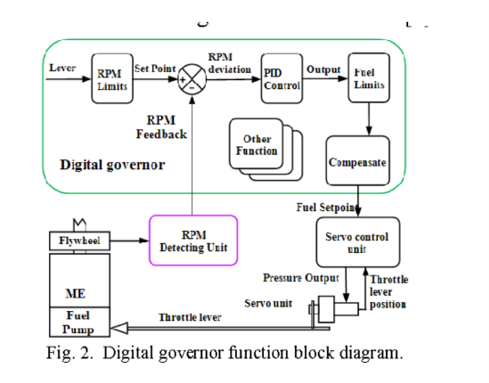
Electronic Governor Function Block Diagram
The digital governor function block diagram on page 9 illustrates the closed-loop control arrangement.
It shows:
Flywheel → RPM Detection Unit → RPM Feedback → Set Point Comparison → PID Control → Fuel Limits → Compensation → Servo Control Unit → Fuel Pump
This diagram demonstrates how engine speed is continuously measured and compared with the desired setpoint before the fuel-control command is generated.
Advantages of Electronic Governors
According to the provided material, electronic governors provide several important advantages.
Improved Precision
Electronic governors provide more accurate speed regulation and smoother engine operation. They can reduce harmful speed fluctuations caused by rough seas and changes in ship loading.
Improved Fuel Efficiency
Real-time fuel-control adjustment can reduce unnecessary fuel consumption, helping reduce operating costs and emissions.
Remote Control and Automation
Electronic governors can provide diagnostic functions and can be integrated with an Engine Management System (EMS) or other ship control systems.
This can support:
- Remote monitoring
- Data logging
- Automated control
- Bridge-based control functions
Different Control Modes
Electronic governors can operate in different modes, including:
- Isochronous mode
- Droop mode
This allows speed-control characteristics to be selected according to operational requirements.
Safety Functions
Modern electronic governor systems may include features such as:
- Overload protection
- Overspeed shutdown
- Backup control arrangements in some electro-hydraulic systems
Governor Used in Auxiliary Engine and Main Engine
According to the provided study material:
Auxiliary Engine
The A/E governor is a droop-speed governor with an overspeed trip.
Droop is used because it provides the required load-sharing capability when generator sets operate in parallel.
Main Engine
The M/E governor is described as a constant-speed or isochronous governor with an overspeed trip.
What Is an Isochronous Governor?
An isochronous governor is a constant-speed governor.
The term is explained in the provided material as:
- Iso = equal
- Chronous = time
Therefore, the concept refers to equal time for each engine revolution, meaning constant engine speed.
An isochronous governor attempts to maintain constant engine speed despite changes in load and power.
After a load change, there may be a short period during which the governor stabilizes the engine speed before it returns toward the original value.
What Is an Overspeed Trip?
An overspeed trip is an independent safety device designed to cut off fuel supply when engine speed exceeds a predetermined limit.
It provides additional protection if the normal governor fails or does not respond quickly enough.
According to the provided material, the overspeed protection is intended to stop the engine/turbine when RPM exceeds approximately 10% above normally rated RPM.
Causes of Engine Overspeed
The PDF identifies several possible causes:
1. Sudden Removal of Load
For example, the propeller may come out of the water in rough weather, causing a sudden reduction in load.
2. Stuck Fuel Control Shaft
A stuck fuel-control shaft can prevent the fuel supply from reducing when required.
3. Governor Failure
The normal governor may fail or may not respond quickly enough during an emergency.
Mechanical Overspeed Trip
A mechanical overspeed trip can use a weighted, spring-loaded bolt installed in a rotating engine shaft.
When the engine speed becomes excessive, centrifugal force on the bolt increases.
When this force exceeds the preset spring force, the bolt moves outward and operates a latch. The latch releases a plunger that shuts off fuel supply to the engine.
The mechanical overspeed-trip diagram on page 12 shows the spring-loaded bolt, rotating shaft, latch and fuel shut-off mechanism.
Suggested figure caption:
Figure 4: Mechanical overspeed trip using a spring-loaded centrifugal bolt to shut off fuel.
Electro-Pneumatic Overspeed Trip
The provided material describes an electro-pneumatic overspeed trip used on Wärtsilä engines.
A spring-loaded pneumatic cylinder is fitted at each fuel pump. When an overspeed trip occurs, the fuel-pump rack is moved to the no-fuel position.
During normal operation, the spring keeps the operating end of the rod clear of the fuel-rack pin.
When overspeed occurs, the solenoid valve admits air into the cylinder. The piston moves against the spring force and pulls the fuel-rack pin to the shut-off position, completely stopping fuel supply.
Electronic Overspeed Protection
Electronic overspeed protection uses:
- Measuring gear or surface
- Magnetic speed sensors
- Measuring system
- Trip logic
- Relay outputs
The sensors detect the rotating surface and produce pulse signals. The measuring system determines engine speed by measuring the time between pulses.
Benefits
The system provides:
- Accurate speed measurement
- Easy calibration
- Easy testing
- Simple set-point configuration
- Protection against unauthorized programming through a key-lock arrangement
Mechanical vs Hydraulic vs Electronic Governors
| Feature | Mechanical Governor | Hydraulic Governor | Electronic Governor |
|---|---|---|---|
| Operating principle | Centrifugal force | Flyweights + hydraulic control | Electronic feedback |
| Main sensing method | Mechanical flyweights | Mechanical flyweights | Magnetic pickup/speed sensor |
| Control mechanism | Mechanical linkage | Hydraulic power piston | ECU + actuator |
| Sensitivity | Relatively lower | Higher | High precision |
| Power for fuel control | Limited | High | Controlled through actuator |
| Complexity | Simple | More complex | Electronic and control-system based |
| Main advantage | Simple and inexpensive | High power and efficiency | Precision and fast control |
| Feedback | Mechanical | Hydraulic/mechanical | Electronic closed loop |
This comparison summarizes the governor arrangements described in the supplied PDF.
Governor Working in Simple Steps
For quick understanding, the complete governor operation can be remembered as:
Step 1: Engine Speed Is Set
A desired engine speed is established.
Step 2: Speed Is Sensed
The governor detects the actual engine speed.
Step 3: Speed Is Compared
The governor determines whether the engine speed is above or below the required value.
Step 4: Fuel Supply Is Adjusted
The fuel-control mechanism increases or decreases fuel supply.
Step 5: Engine Speed Changes
The engine responds to the change in fuel supply.
Step 6: Governor Stabilizes
The governor settles into a new equilibrium condition and maintains stable operation.
This basic feedback concept applies to the mechanical, hydraulic and electronic governor arrangements described in the source material.
Importance of Governors in Marine Engineering
Governors are essential for reliable operation of marine diesel engines because they:
- Maintain engine speed within the required range
- Respond to changing engine loads
- Control fuel supply
- Improve operational stability
- Help prevent excessive speed fluctuations
- Support load sharing in generator applications
- Provide overspeed protection when combined with an overspeed trip
Electronic governors can additionally provide monitoring, diagnostics and integration with ship automation systems.
Frequently Asked Questions About Marine Engine Governors
What is the function of a governor?
The governor automatically controls engine speed by regulating fuel supply according to load changes.
What is governor hunting?
Hunting is the fluctuation of engine speed above and below the mean operating speed.
What causes governor hunting?
Common causes given in the material include excessive sensitivity, incorrect compensation settings, air in the hydraulic system and worn linkages.
What is speed droop?
Speed droop is the reduction in engine speed between no-load and full-load operation, expressed as a percentage of no-load rated speed.
Why is droop used in auxiliary engines?
The provided material states that droop is used to obtain load-sharing capability when generator sets operate in parallel.
What is an isochronous governor?
An isochronous governor is a constant-speed governor designed to return the engine to its original speed following a load change.
Pingback: Marine Emergency Generator: SOLAS Rules & Shipboard Guide (60 characters) - Fleet Frontier