

TURBOCHARGER
Shown in the sketch is a section of turbocharger fitted on a large 2 stroke engine. It consists of a single stage, axial flow exhaust gas driven turbine mounted on a common shaft with centrifugal air compressor.
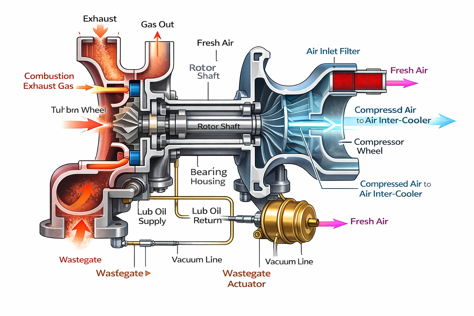

Turbine: The exhaust gas enters through the nozzle ring and is then directed to the turbine rotor blades at high velocity. The nozzle ring converts the energy in the exhaust gas to kinetic energy. The turbine blades are firmly fitted on the wheel by fir tree shaped roots which give positive fixing and minimum stress concentration.
The blades are held together at the free end by lace wire to dampen vibration. The nozzle ring, turbine wheel, blades and rotor shaft are manufactured from heat resisting nickel chrome alloy steel to withstand high working temperatures. The turbine casing is made of cast iron with adequate water-cooling spaces. In modern slow speed 2 stroke engines with relatively low exhaust gas temperatures the casings are uncooled.
Blower: The air blower casing is fitted with filters and silencers at the air inlet of the casing. An inducer is fitted just before the impeller to direct the flow of air to the centre of the impeller without any shock. The impeller takes in air axially and delivers it radially through a diffuser to the volute casing. The kinetic energy is converted into pressure energy and air is delivered to the air cooler for cooling and then to scavenge manifold. The impeller is made of light aluminum alloy. Compressor casing is of cast aluminum and un-cooled.
Bearings and lubrication: Two shaft bearings are fitted, one at each end. End thrust is taken at the compressor bearing, allowing the turbine bearing free thermal expansion of the shaft.
Bearings may be of either
- Plain sleeve types with copper lead bushes on hardened steel sleeves
- These are lubricated by external L.O supply system.
- From a main L.O pump, leading to the bearings with a separate L.O pipeline. It has also a gravity tank in case of failure of L.O supply. (Under main engine L.O system).
- The head from the gravity tank is sufficient to produce a continuous supply of oil to the turbocharger bearings and the capacity should be such that the bearings will not be damaged, should both lubricating oil pumps break down.
- The gravity tanks should have capacity, which will permit the turbochargers to run for approximately 15 minutes
- ball and roller type.
- Ball and roller bearings may be lubricated by self-contained gear type pumps, operated from the shaft and drawing oil directly from the independent bearing sump.
Labyrinth Seals: Two labyrinth seals are fitted to the shaft, one between thrust bearing and air compressor and the other between turbine and bearing. They are sealed with air under pressure from the compressor discharge through internal passages. The seals prevent possible oil leakage into the turbine and compressor and prevent exhaust gas leakages into bearing oil.
Maintenance on Turbochargers:
- Regular checking of oil level in bearing sump and changing oil after 1000 hrs
- Cleaning of air filter after 1000 hrs.
- Renewal of bearings after 16000 hrs. and gear pumps to be renewed or reconditioned after 16000 hrs.
- The cooling water chamber to be cleaned at every 8000 hrs.
- Regular water washing of compressor and turbine.
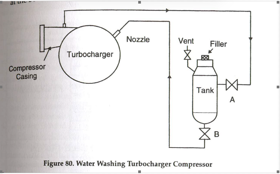

Turbocharger Cleaning: Under operating conditions turbocharger systems may become fouled, causing reduced efficiency, loss in power and surging.
Compressor:
Oil mist and dust drawn from the engine room may get deposited on the compressor surface. Dirt deposits should be dislodged by injection of water during operation.
A small container is provided which is filled with water to clean the compressor. Water is injected using air from the compressor. Cleaning is carried out at full load and performed once every day.
- Open filler of the tank and fill with fresh water. Close vent.
- Open air supply valve A
- Open injection valve B and wait for 30 seconds.
- Close valve A and B and open vent.
- Check to ensure the tank is empty.
Turbine:
Fouling of the turbine can occur due to products from combustion of fuel, ash and any other non-combustibles present in the fuel.
Water Washing of Turbine side: The dirt deposits on turbine side can be reduced by periodic cleaning (water washing) during operation. Dirty turbines lead to higher temperatures of exhaust gas and higher stresses on bearings due to imbalance.
- The engine speed must be reduced to reduce the exhaust temperature and prevent thermal shock of the turbine.
- Once the exhaust temperature is at or below the manufacturer’s limit, the turbocharger drain can be opened and freshwater admitted to the turbine casing.
- Water should be admitted slowly until water appears at the drain; then the water flow can be increased.
- Water supply and drain to be closed once clean water starts flowing from the drain.
- After the cleaning is completed, the engine must be run at the same speed for about 5 minutes until all parts are dry.
This operation is usually carried out on a weekly basis.
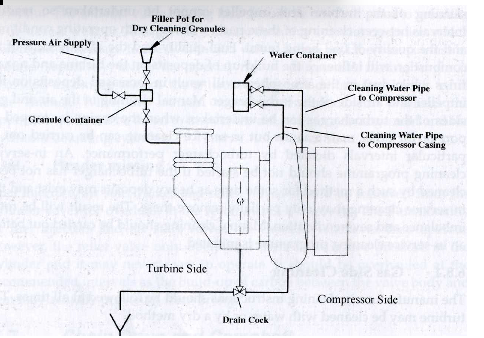

Dry Cleaning: Carbon particles stick inside the Turbocharger and are not easy to remove. To make the removing job easier dry cleaning of the turbo charger is carried out.
The turbocharger speed does not have to be reduced when dry cleaning. A container is filled with correct amount of cleaning material, either marine grit (ground walnut shells) or small grains of rice. The valve from the container is then opened to blow the material into the turbine casing. This is carried out normally every two days.